Seasteading tech for ten thousand startup countries our best chance for liberty
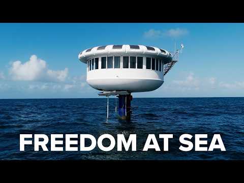
The Seasteads are Here
Learn about the revolutionary technology for eco-restorative ocean communities and our plan to secure political autonomy for all seasteaders.
The Seasteading Institute is a nonprofit organization.


Our mission is to enable floating societies which will allow the next generation of pioneers to test new ideas for government.
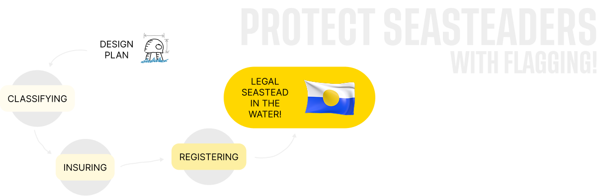
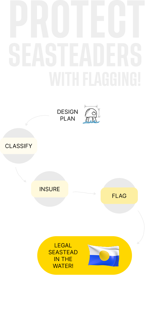
A maritime flag offers government protection without government control. It's a glorious legal hack.
We are raising money to fund our quest for a maritime flag. We have a five-year plan to create a Classification Society to ensure that seasteads are safe and recognized by the family of nations.